Step2: Basic Usage of RT-SystemEditor and Testing Audio Components
In this step, we will directly connect the audio input and the audio output component and verify that the components are working properly.
Preparation
- Download and install eclipse with RT-SystemEditor.
- On Ubuntu, please refer to the instruction on this page: http://openrtm.org/openrtm/en/node/945
- On Windows, please download and install the OpenRTM-aist-Python package provided from this page: http://openrtm.org/openrtm/en/node/949#toc3
- Prepare a microphone and a speaker (earphone and headphone) connect to PC.
- Create rtc.conf file.
Create a configuration file “rtc.conf” and save to working directory. Content of rtc.conf is as follows
corba.nameservers: localhost:9876
naming.formats: %n.rtc
logger.file_name:stdout
On Windows, rtc.conf file is alread allocated by the installer.
- Launch the name server.
Start the name server with port number as specified in rtc.conf file. (In the above example 9876)
$ rtm-naming 9876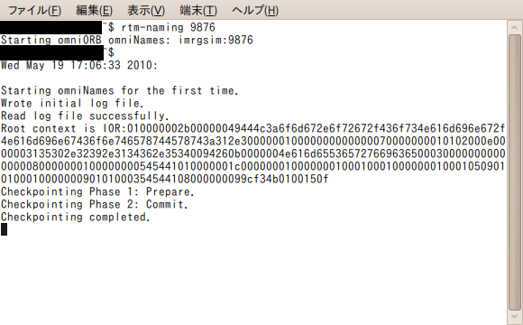
- Launch eclipse with RT-SystemEditor installed.
Basic usage of the RT-SystemEditor
In this section, we describes the basic usage of the RT-SystemEditor and test audio components.
Launch AudioInput and AudioOutput components.
Warning
If you are using ubuntu 9.10 or later, please use PulseAudioInput and PulseAudioOutput components. If you are using version older than 9.10, please use PortAudioInput and PortAudioOutput components.
- ubuntu9.10 or later: enter the following commands on each terminal.
$ pulseaudioinput
$ pulseaudiooutput
- older version: enter the following commands on each terminal.
$ portaudioinput
$ portaudiooutput
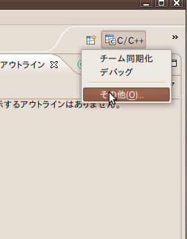
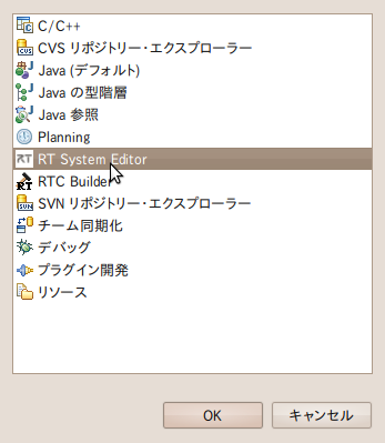
Open the eclipse RT-SystemEditor perspective.
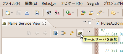
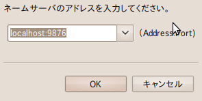
Select “Add name servers” button and register the name servers specified by the rtc.conf file.
(In above example “localhost:9876”)
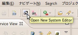
Click the icon on the left to open the new editor screen.
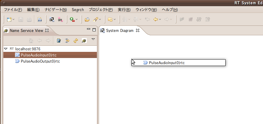
From the name service views (left panel) drag and drop the AudioInput (and AudioOutput) component to the editor screen.
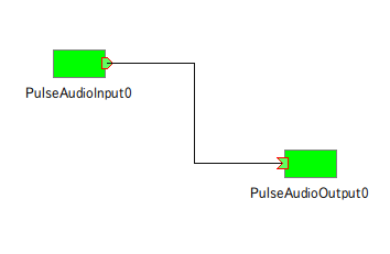
Connected the dataport between the components.
Click the connector part of the data port.
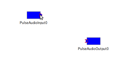
Drag to the other data port.
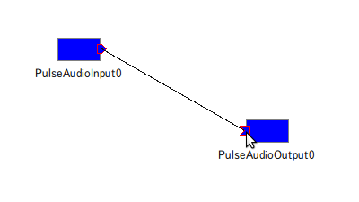
When you drop the link, a connection settings dialog will appear. No configuration change is required.
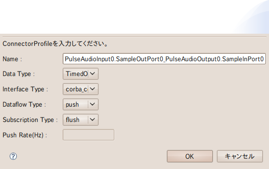
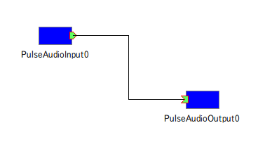
Press OK (connector changes to green color)
Activate the component and check the operation
Activate all components.
Press “All Activate” button.
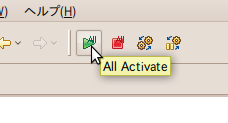
AudioInput and AudioOutput activate and change from blue to green.
Verify the operation.
Verify that sound input entered from the microphone is played from speakers.
In this step we have learned basic usage of the RT System Editor through testing the audio components.
Proceed to Step3: Testing Voice Synthesis Component.